
Sheet metal prototyping is the fastest way to validate form, fit and production behaviour for metal parts before you commit to tooling. It works by cutting, bending and joining production alloys, mild steel, aluminium, stainless, using processes like laser cutting, waterjet, CNC punching and press braking. Done right, following ISO 9001 quality practices and standard DFM review, it delivers assembly-accurate, production-representative parts in days rather than months.
TL;DR:
- Sheet metal prototyping is most valuable when testing load-bearing, functional, or forming aspects with production-grade materials, avoiding misleading results from substitutes.
- Laser cutting is the fastest and most cost-effective method for simple profiles, while waterjet and EDM suit complex shapes and thick or heat-sensitive materials.
- Proper material selection and adherence to design for manufacturability rules, such as minimum bend radius and hole placement, are critical to avoiding delays and costly rework.
- Combining all manufacturing steps—cutting, forming, joining—within one shop reduces risk, streamlines the workflow, and ensures consistent quality from prototype to production.
- Early DFM review and proper packaging of CAD files prevent common errors, save time, and make the transition from prototype to scaled production more efficient.
Table of Contents
- When does sheet metal prototyping make sense?
- Cutting, forming and joining: choosing the right process combination
- Materials and gauges: getting the alloy and thickness right
- Design for manufacturability: rules that prevent a second iteration
- Lead time and cost: what actually drives your prototype budget
- From CAD file to first article: a workflow that survives the handoff to production
- Why EMUSKI's approach to prototyping matters
- What most engineers get wrong about prototyping
- Get a prototype quote that already accounts for production
- Sources
- FAQ
When does sheet metal prototyping make sense?
Sheet metal prototyping earns its place whenever you need a part that behaves like the production version, not just looks like it. Enclosures for electronics, structural brackets, chassis panels, HVAC ductwork, and cosmetic front-panel samples all fall into this category. So do pilot-run parts destined for a small batch before full tooling gets signed off.
The decision usually comes down to five questions. Answer them honestly before you send a file to a shop, and you'll save yourself a wasted iteration.
- Does the test require production-grade material? If you're checking thermal expansion, fatigue, or structural load, substitute materials will mislead you.
- How many iterations do you expect? One-shot cosmetic checks tolerate looser tolerances than a part heading into three rounds of fit testing.
- Are you testing fit, function, or both? A bracket that only needs to slot into an assembly has different acceptance criteria than one carrying a load.
- What's your schedule? Laser-cut, formed parts can turn around in days; anything needing hard tooling (progressive dies, deep draws) adds weeks.
- What's the cost ceiling per iteration? Waterjet and EDM cost more per part than laser cutting, so reserve them for features laser cannot achieve.
If your part is small, geometrically complex, or needs internal cavities, additive manufacturing or CNC machining from billet often beats sheet metal for that first proof-of-concept. Sheet metal prototyping wins once you need thin-wall, folded, or welded geometry that mirrors how the final part will actually be made. Highland Machine notes that catching manufacturing issues at the prototype stage avoids the far higher cost of discovering them during a production run.
Cutting, forming and joining: choosing the right process combination
Every sheet metal prototype starts with a cutting decision, moves through forming, and often ends in some form of joining. Getting each stage right, rather than defaulting to whatever the shop runs most often, is what separates a useful prototype from an expensive guess.
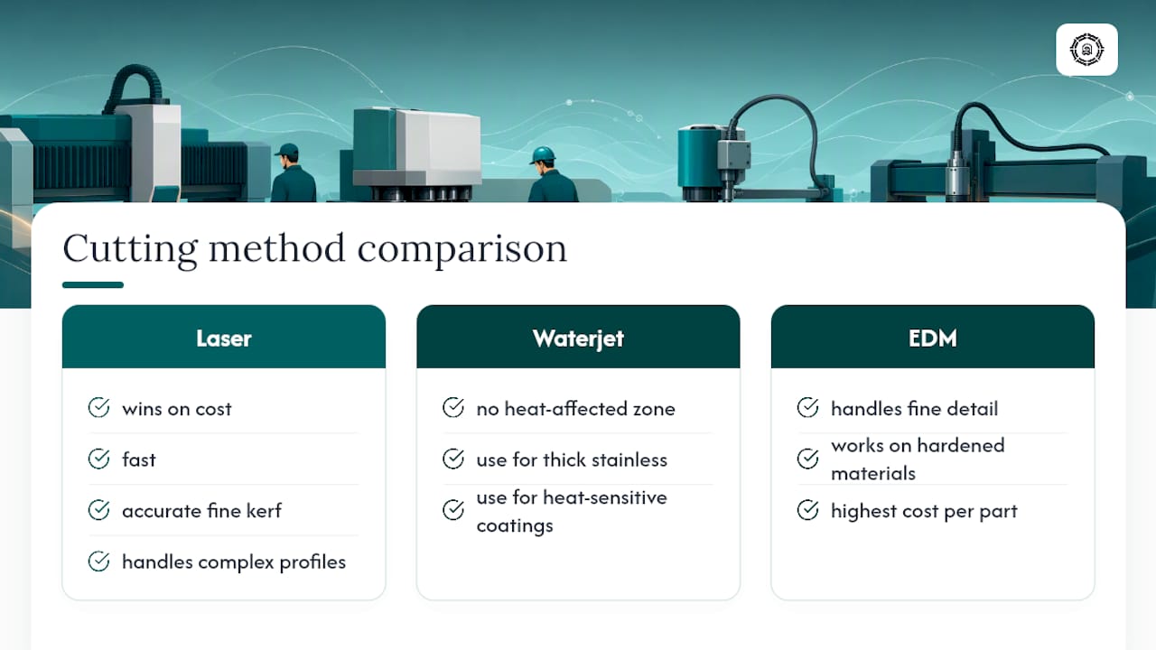
Cutting. Laser cutting is the default for most flat-pattern work: it's fast, accurate to a fine kerf, and handles complex profiles without dedicated tooling. Waterjet cutting introduces no heat-affected zone, which matters for thick stainless or heat-sensitive coatings. CNC punching suits repeat features (hole patterns, louvres) across multiple parts, and wire EDM handles fine detail or hardened materials that laser and waterjet struggle with.
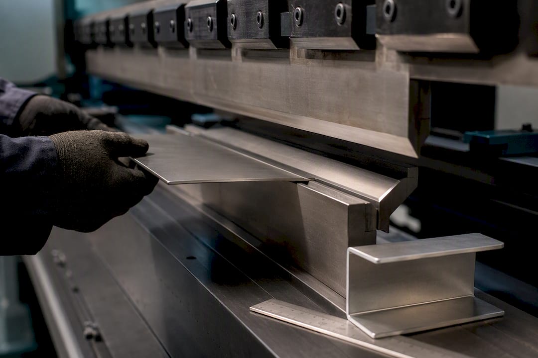
Forming. Press brake bending dominates prototype forming. The bend allowance depends on the material's k-factor, a ratio describing where the neutral axis sits within the material thickness during a bend. Bend sequence matters too: forming the wrong flange first can trap a subsequent bend against the brake's tooling. Springback, where the metal relaxes slightly after the punch retracts, is the most common source of out-of-spec angles, and experienced shops overbend to compensate.
Joining. MIG welding is fast and strong but leaves visible beads; TIG gives a cleaner finish for visible joints at the cost of speed. Spot welding suits lap joints on thinner gauges. Rivets and PEM inserts (self-clinching fasteners pressed into pre-punched holes) avoid heat distortion entirely, useful when you need a threaded feature without a secondary tapping operation. For cosmetic-only samples, some shops mock weld seams with adhesive or filler rather than running a full weld, saving time when structural strength isn't being tested.
Pro Tip: If you're only validating fit and cosmetic finish, ask your shop to skip structural welds and use temporary fasteners instead. You'll get the visual and dimensional check you need in half the time, and the shop can quote a genuine weld once the design is frozen.
As a rough selection matrix: laser cutting wins on cost and speed for straightforward profiles, waterjet wins when heat distortion is unacceptable, and EDM wins on fine detail at the highest cost per part.
Materials and gauges: getting the alloy and thickness right
Material choice is where a lot of prototypes quietly go wrong, because a part that looks identical in a different alloy can behave completely differently under load or during forming. Shincofab points out that matching production materials is essential for functional testing, and substitutes should be reserved for cosmetic checks only.
The common choices each carry trade-offs:
- Aluminium 5052 forms well with a generous bend radius and resists corrosion, making it a strong default for enclosures and brackets that don't need high strength.
- Aluminium 6061 is stronger but less forgiving in tight bends, often requiring a larger minimum bend radius to avoid cracking.
- Cold-rolled steel (CRS) is cheap and forms predictably, a solid choice for structural prototypes where cosmetic finish isn't critical.
- Stainless 304 resists corrosion and looks good unfinished, but work-hardens faster during bending, which can affect springback across a batch.
- Stainless 316 adds better chemical resistance for parts destined for harsher environments, at a material cost premium.
Gauge thickness directly drives your minimum bend radius and how much springback to expect. Thicker material needs a larger radius or it risks cracking at the bend line, and tooling choices shift accordingly, thinner gauges tolerate tighter radii and smaller press brake dies.
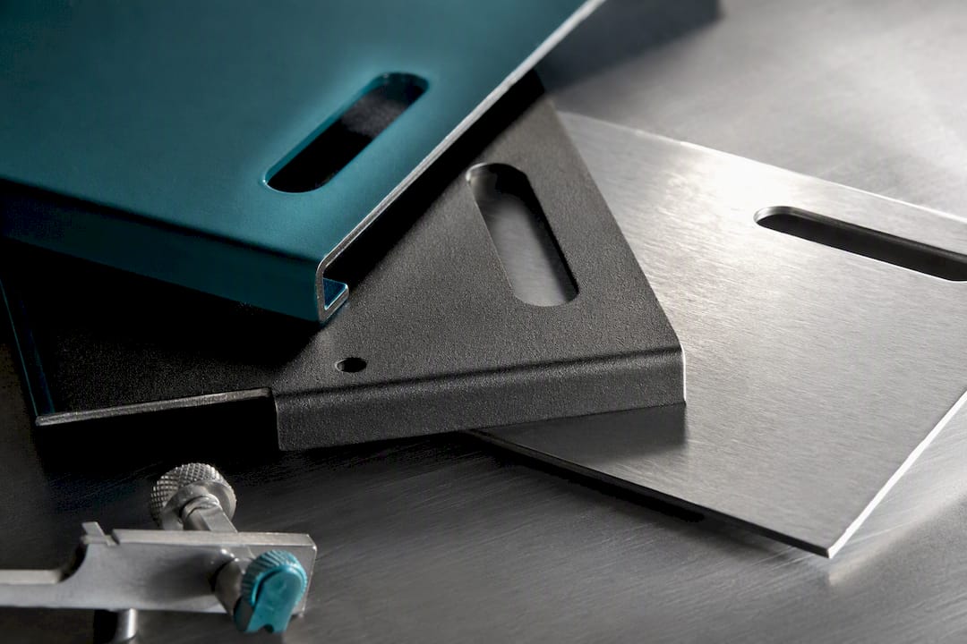
Finish choice matters more than most engineers assume. If your final part will be powder-coated or anodised, prototyping with the same finish reveals masking and coverage issues you'd otherwise only find in production. For regulated projects, aerospace or medical device work in particular, ask for mill certificates and material traceability on your prototype run, not just the production order.
Design for manufacturability: rules that prevent a second iteration
Most prototype delays don't come from the shop floor. They come from a CAD file that ignores the physical limits of forming and cutting. Building these rules into your design before the first quote request saves a full iteration cycle almost every time.
- Set your minimum bend radius by material. As a rule of thumb, keep the bend radius at least equal to material thickness for mild steel, and 1 to 1.5 times thickness for aluminium alloys prone to cracking.
- Keep holes clear of bends and edges. A hole placed too close to a bend line distorts during forming; a common guideline is keeping hole centres at least 2.5 times material thickness from the bend line, and at least 2 times thickness from a cut edge.
- Respect minimum flange length. A flange shorter than roughly 3 to 4 times material thickness plus the bend radius risks being crushed or bent inconsistently by the brake tooling.
- Use the correct K-factor for your bend allowance calculation. Getting this wrong is the single most common cause of a flat pattern that doesn't fold up to the right final dimension, a point echoed in SMS Laser's guidance on prototype DFM review.
- Decide where tolerances actually matter. Call out tight tolerances only on functional datums, mating surfaces, hole patterns that must align with another part, and relax everything else to standard shop tolerance.
- Consolidate parts where possible. Every extra bend or separate piece adds a setup step and a chance for error; a single folded bracket often beats a welded assembly of three flat pieces.
- Use tabs and slots for self-locating assemblies. This reduces reliance on jigs during welding or riveting and improves repeatability across iterations.
Pro Tip: Before you send a quote request, ask the shop three questions: what's your standard tolerance on formed features, do you provide free DFM feedback at quoting, and can you flag any features that will need a secondary operation? Their answers tell you more about fit than any brochure.
Lead time and cost: what actually drives your prototype budget
Sheet metal prototype pricing is driven less by part size than by process complexity. Material cost is usually the smallest line item; the real cost drivers are the operations stacked on top of it.
Cutting method matters first: waterjet and wire EDM cost more per part than laser cutting because they run slower and often need more setup. Secondary operations, welding, powder coating, anodising, deburring, add both cost and calendar time, and each one is a handoff to a different station or sometimes a different vendor. Inspection adds cost too, particularly first-article dimensional checks with a CMM (coordinate measuring machine) rather than a hand gauge. Iteration count compounds everything: a part that goes through three rounds of tweaks costs roughly three times the setup, even if the part itself is cheap to cut.
Single-piece prototypes on laser-cut, formed sheet metal commonly turn around in a matter of days once a design is DFM-approved; small-batch runs of a few dozen parts stretch that timeline depending on secondary operations and finishing queues. Rush options exist at most shops but usually carry a premium, since they mean bumping your job ahead of scheduled production work.
Three tactics reliably cut both cost and time:
- Standardise on one or two gauges across your part family instead of speccing a different thickness for every bracket.
- Batch your design iterations rather than sending single-feature changes one at a time.
- Accept an unfinished or substitute-material mock-up for a pure cosmetic or fit check, and reserve the production-spec material for your functional prototype.
From CAD file to first article: a workflow that survives the handoff to production
A repeatable workflow prevents the most common failure mode in prototyping: engineering work that has to be redone from scratch once the part moves to volume production.
- Package your files properly. Send native CAD alongside neutral formats (STEP or IGES), a flat pattern, bend notes showing direction and angle, and clear GD&T with material callouts including gauge and alloy.
- Go through a DFM review before cutting starts. A competent shop should return specific, documented feedback, flagged bend radii, hole clearances, tolerance conflicts, not a generic sign-off. Document every revision request in writing so the change history is traceable later.
- Request first-article inspection. Ask for critical dimensions checked against your drawing, an assembly verification if the part mates with others, and surface acceptance criteria if finish matters. This is where PPAP-style checks (Production Part Approval Process) or a formal FAIR (first article inspection report) earn their keep on regulated projects.
- Hand off engineering data cleanly when scaling. Moving from prototype to pilot production works best when the same shop retains your revision history, material certificates, and inspection records, rather than starting a new vendor relationship from a blank file.
Why EMUSKI's approach to prototyping matters
A single ISO-certified shop running both prototype and production work can provide DFM feedback at quoting that reflects the actual tooling for the part rather than a generic estimate. Some manufacturers combine rapid prototyping and on-demand manufacturing with AI-driven cost estimation to provide realistic cost insights between a first article and a production run before commitment.
- Single-shop path from prototype to scaled production, reducing the risk of process drift between the two.
- DFM feedback built into the quoting stage, not bolted on afterwards.
- Dimensional inspection and traceability records that carry forward into pilot and volume runs.
- Strategic sourcing input for teams weighing material or supplier trade-offs before scaling.
Engineers weighing a prototype run can request a quote or DFM review directly through Emuski's service pages.
What most engineers get wrong about prototyping
The conventional advice treats sheet metal prototyping as a formality, cut a part, check it fits, move on. That undersells what a good prototype run actually does: it's the cheapest place in the entire product development cycle to catch a bend allowance error, a tolerance stack-up, or a material substitution that quietly changes how a part performs under load.
Where the standard guidance falls short is in treating all prototypes as equal. A cosmetic mock-up and a functional load-bearing bracket have almost nothing in common, yet plenty of engineering teams spec them with the same tolerance and the same material, wasting either time or money depending on which way they err. Matching the rigour of the prototype to the actual question you're asking it is the single highest-leverage decision in the entire process.
If there's one priority worth fixing first, it's DFM review. Skipping it to save a week routinely costs two weeks later, once a flawed flat pattern reaches the brake and springs back wrong. Build the review in early, and everything downstream, cost, schedule, and the eventual handoff to production, gets easier.
— Nya
Get a prototype quote that already accounts for production
Emuski is the alternative to juggling separate prototype and production vendors: one ISO-certified shop runs your first article and your scaled build, so the DFM feedback, tolerances, and material data from the prototype carry straight into the production quote instead of getting redone from scratch.
That matters most when a design goes through several rounds of iteration, because every handoff between vendors is a chance for a bend allowance or a tolerance call to get lost in translation. Emuski's rapid prototyping and manufacturing services cover laser cutting, forming, welding, and finishing under one roof, backed by AI-driven cost estimation that shows you where a design change will move your production cost before you commit to it. If your project involves a should-cost analysis or DFM optimisation ahead of tooling, Emuski's cost engineering services can run that alongside the prototype build. CAD files and drawing packages can be sent through service pages of relevant manufacturers to start a DFM review and obtain a quote scoped to the actual part.
FAQ
What are the four types of prototyping?
Product development generally recognises four categories: proof-of-concept models, working prototypes, visual or cosmetic prototypes, and functional prototypes built close to production specification. Sheet metal prototyping most often serves the functional and working categories, since it uses the actual forming and joining methods a production part would go through.
What is sheet metal design?
Sheet metal design is the practice of engineering parts made from flat metal stock that gets cut, bent, and joined into a final shape, governed by rules around bend radius, hole placement, and flange length that keep the flat pattern manufacturable. Good sheet metal design accounts for springback and k-factor before the file ever reaches a press brake.
What are the 7 common methods of metal processing?
Shops commonly rely on laser cutting, waterjet cutting, CNC punching, CNC bending (press braking), rolling, welding, and stamping, as Shincofab's overview of sheet metal prototyping sets out. Each method suits different combinations of accuracy, material thickness, and production volume.
What are the two types of sheet metal?
Sheet metal is broadly split into ferrous types, such as cold-rolled steel and stainless steel, and non-ferrous types, primarily aluminium alloys like 5052 and 6061. The choice between them depends on strength requirements, corrosion resistance, weight targets, and how the part will be formed.
How much does sheet metal prototyping cost through Emuski?
Emuski's rapid prototyping and manufacturing services don't carry a published flat rate, since cost depends on material, process, and iteration count. Current pricing is available by requesting a quote directly through Emuski's manufacturing services page.